
Workflow Overview#
The general workflow for additive manufacturing (3D printing) is typical of all code driven manufacturing like CNC, Cricut, Laser Cutters, CNC routers and others. For our purposes I’m going to going to suggest we think of the workflow as having three (3) broad stages.
I: Design#
In the context of modern manufacturing and 3D printing the starting point is the design of the object. This is commonly accomplished using Computer Aided Design (CAD) tools. CAD tools are amazing and wonderful and have a long and sometimes steep learning curve.
If you are new to 3D printing there is very little reason for you to worry about learning and using CAD software. The reasons for this will become apparent shortly.
OUTPUT:
The output of this stage of the workflow is generally an stl file (.stl). This is the file type that is most commonly passed to the next stage of the workflow.
II: Slicing#
A transformative idea from the beginings of 3D printing was the idea that you can take any object and transform it into a stack of individual slices. The manufacturing process then creates each layer sequentially on top of the previous layers. A version of this idea you may have seen is creating a topographic model of a mountain using layers of art board as shown below.
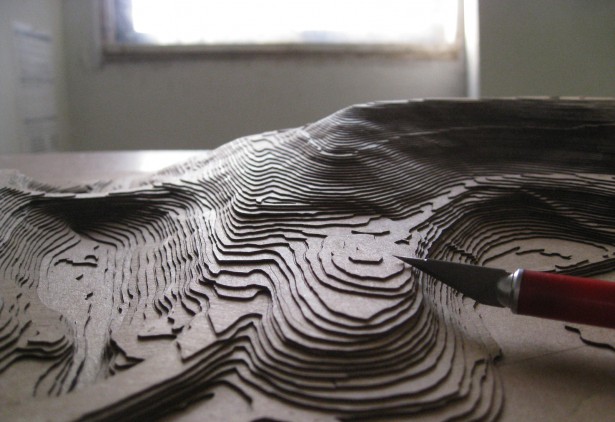
Fig. 13 Topographic Model#
I think this is a helpful way to visualize the slicing process because it also illustrates some of the compromises that are inherent in the 3D printing process.
As with many complex processes like this software is used to create the shape of the layers of the object you want to print. There are a variety of open source and proprietary tools for slicing objects. For almost any object you might wish to print in the library makerspace you will need to execute this step.
OUTPUT:
Once the slices have been created then they need to be translated into the commands that drive the printer. The industry standard for controling manufacturing machines of many types is called gcode. These are a set of commands that the 3D printer (or robot or welder or router) will interpret to create the object. This is a form of computer code and is the final stage of the slicing process. This is the file that is passed to the printer.
III: Printing#
Once you have the ‘gcode’ in hand as a digital file then all that remains is to feed that code to the machine and step back. This would be the ideal of course and the reality is that you might need to prepare the machine in certain ways to be ready to print your object. You might need to load a particular filament or check that the extruder seems to be working correctly. It’a perhaps helpful to think of this a little like your coffee maker. When all goes well you just need add the grounds (or K-cup) and some water and hit the start button. On the other hand, sometimes your coffee maker needs a little more attention or misbehaves in some way. If all goes smoothly you remove the object you have created from the printer, put the printer to bed, and go enjoy what you have made.
OUTPUT:
Not surprisingly the output of the printing process is the printed object. You may not be done at that point since there is the possibility of post processing or removal of supports used in the printing process.
Workflow Summary#
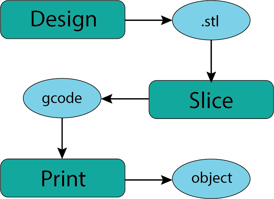
Fig. 14 Workflow#
Now we will take a little closer look at each of these stages in the workflow.